
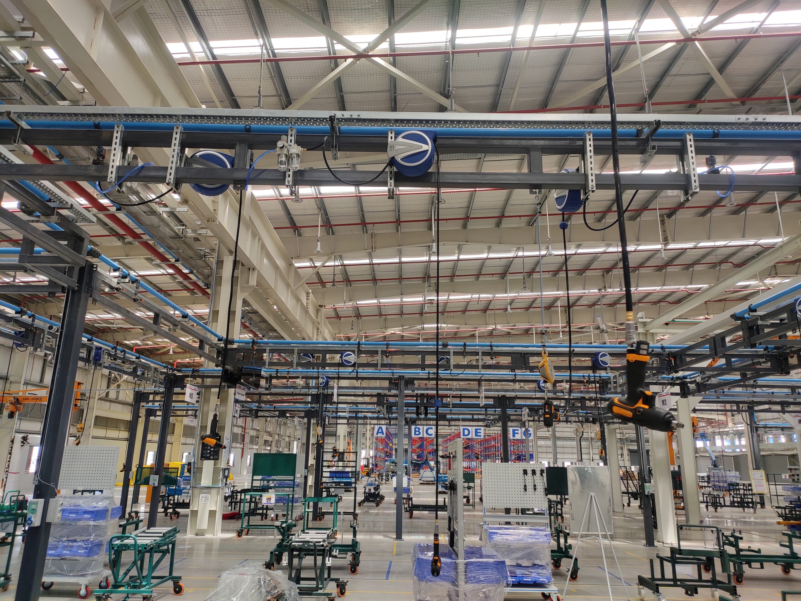
In most factories, compressed air is treated as a utility, expected to be available on demand. Factories often neglect piping networks until problems arise, despite maintaining compressors and major components. For instance, even with normal compressor operation and inconsistent supply at distant machines, one might increase pressure or investigate leaks, yet minor interruptions persist. The problem is usually with the distribution line, not the compressor. Aluminium compressed air pipe systems offer multiple important benefits for industrial users. Compared with traditional GI, MS, or black-iron piping, aluminium provides a cleaner and more flexible air distribution network. Its main advantages include resistance to internal rust, easier installation, future expansion capability, lower maintenance requirements, and healthier air delivery. When comparing aluminium compressed air pipes in India, consider cost per metre, installation time, corrosion risk, leakage, future expansion, air cleanliness, and long-term maintenance. Why Aluminium Is Used in Compressed Air Piping Moisture is common in compressed air piping. Even with dryers, poor maintenance or high humidity introduces water that, within iron-based pipes, causes rust. Rust forms particles that can clog filters or damage valves and tools. Old pipes with rough surfaces disrupt airflow. Aluminium piping prevents rust, maintains smooth internal surfaces, and reduces the risk of contamination. Aluminium air piping uses modular fittings—elbows, tees, reducers, couplers, valves, brackets, and drop points—that support complex networks rather than simple straight runs. Such flexibility helps factories adapt when machines are added, workstations move, or production expands. Modular aluminium piping makes changes easier than fixed welded or threaded lines. Aluminium Pipe vs GI and Steel Pipe GI and steel pipes are traditional for compressed air. They’re durable but heavy, making installation laborious—especially for overhead runs. Cutting, threading, and welding are time-consuming. In contrast, aluminium pipes are lighter, easier to install on longer runs, and use standardised fittings for a neater, faster setup. The advantages of aluminium piping also include easier post-installation changes. Adding an air drop for new equipment is typically simpler with aluminium, requiring only compatible fittings, whereas GI or steel often requires more complex cutting and welding. Such flexibility saves time and secures a system that easily accommodates changing production needs, adding to aluminium’s key benefits: convenience, adaptability, and lasting reliability. Performance Benefits for Industrial Air Distribution Compressed air pipes must supply sufficient air with minimal leakage. Long pipes, sharp bends, small lines, leaks, or rough interiors all reduce delivery. Aluminium piping, when sized correctly, maintains smoother airflow and reduces rust particles, securing steady air for pneumatic tools. Poor piping can cause minor pressure drops, reducing equipment efficiency and productivity. Aluminium pipe alone does not resolve all system issues. Proper pipe sizing, compressor capacity, dryer, filtration, drainage, and leak control are necessary. The right material only supports a sound layout. Get the best performance by pairing aluminium piping with a well-designed network. Plan headers, branches, and drops based on air demand and equipment placement. Installation Advantages of Modular Aluminium Piping Ease of installation is a key advantage of modular aluminium piping. New factories benefit from cleaner lines, while existing plants can upgrade easily. Aluminium’s light weight streamlines overhead work, and modular fittings allow efficient planning for branch and drop points. Network extensions are simple and support frequent layout changes. Systems use aluminium tubes, connectors, bends, tees, reducers, valves, brackets, clamps, and accessories. Selections depend on pressure, size, layout, and air points. Install with proper supports, minimal bends, and accessible drops to simplify future maintenance. Maintenance Savings Across Time Maintenance often reveals the essential benefits of aluminium piping over traditional materials. Old GI or steel lines may look strong but can conceal rust, scaling, leaks, and difficult modifications. Aluminium compressed air pipes solve these problems by eliminating rust, minimising contamination, requiring fewer repairs, and speeding up changes due to their modular design. These advantages mean lower downtime and easier maintenance. No system is maintenance-free. Testing for leaks, managing condensate, replacing filters, and monitoring pressure are important. Aluminium minimises corrosion-related maintenance and simplifies future upgrades. Best Applications for Aluminium Compressed Air Pipe Aluminium compressed air piping offers several clear advantages for a wide range of industrial and commercial applications. Its suitability includes manufacturing plants, machine shops, automotive workshops, packaging units, textile facilities, electronic assemblies, food processing support, and general factory utilities. Main benefits include flexibility in layout changes, reduced contamination from rust-resistant materials, and reliable clean-air delivery for sensitive equipment such as tools, valves, and machines that require air quality. Buyers in India compare modular aluminium piping with traditional materials to see if it fits their needs. Aluminium is the top choice where clean installation, corrosion resistance, straightforward expansion, and low maintenance matter most. Buyer Checklist Before Asking for an Aluminium Pipe Quotation Before requesting a quote, note the site and system details. List compressor capacity, working pressure, and the distance to usage points. Count air-using machines or workspaces and consider future needs. Review the layout for long routes, bends, or poor drop placement that could cause pressure loss. Plan pipe supports, especially for overhead lines. Check whether pipes will be exposed to moisture, oil, dust, or heat, and decide on additional filtration if needed. A full quote should list pipe sizes, tube types, fittings, valves, connectors, clamps, supports, drop points, and needed accessories. Choose blue and grey aluminium alloy tubes to suit the application and layout. Conclusion An aluminium compressed air pipe is an excellent choice for factories seeking a cleaner, lighter, and more flexible distribution system. Unlike traditional GI, MS, or black iron piping, it offers superior corrosion resistance, easier installation, future expansion, and simplified maintenance. In older plants, aluminium piping can replace rust-prone, hard-to-modify lines. For new plants, it enables a well-organised air network from the outset. Final performance depends on proper planning. Carefully select pipe size, layout, air demand, pressure requirements, and accessories. With a well-designed system, aluminium piping provides reliable air distribution throughout the facility. Browse our range of aluminium alloy blue and grey tubes and compatible accessories. To design the right system for your facility, contact our team for a quotation
INTEC 2026, Coimbatore: A Memorable Exhibition for ShiftAir Transmission Pvt. Ltd.
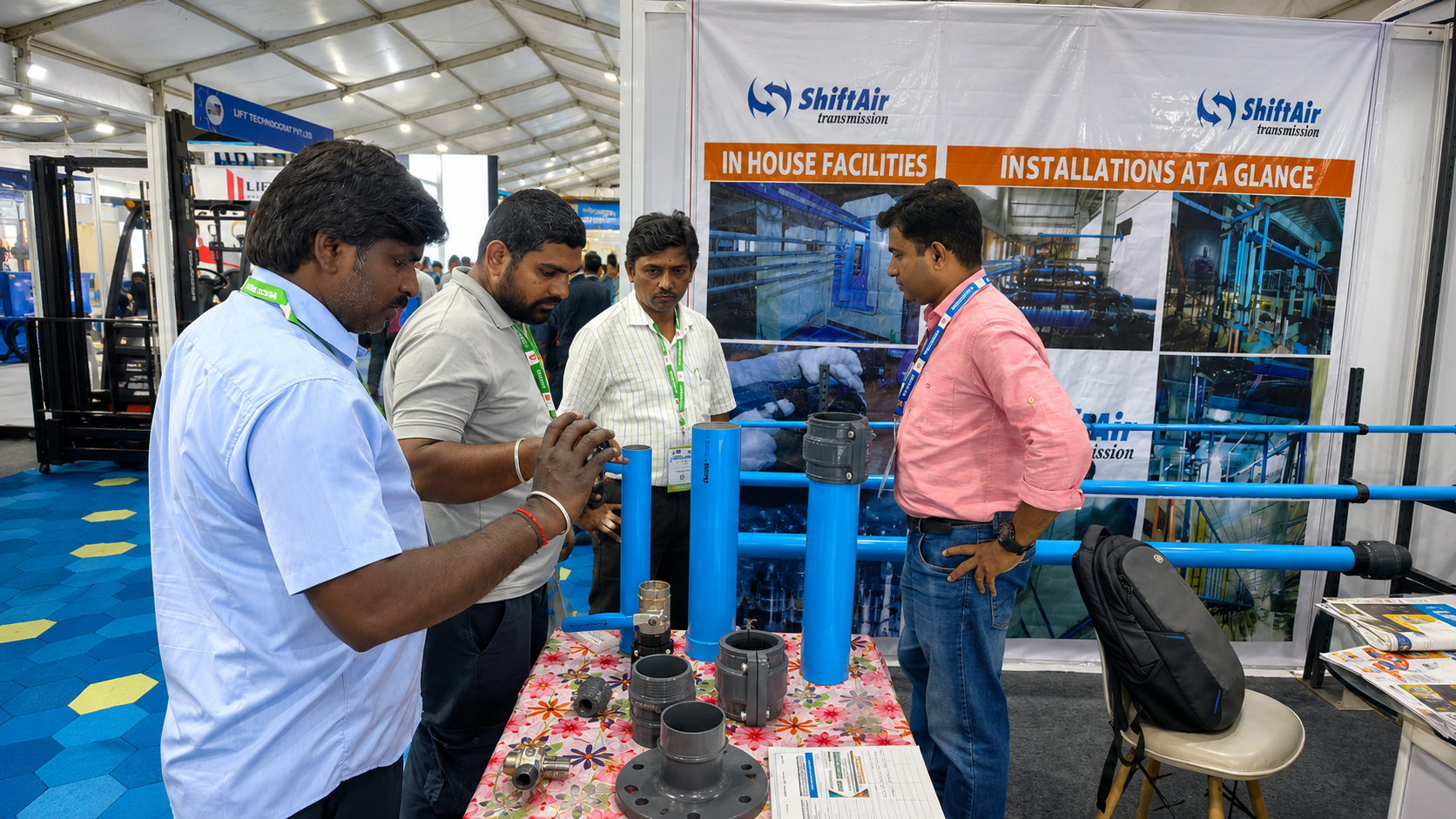
Industrial exhibitions are not just about setting up a booth, displaying products, and meeting visitors. They are about real conversations, new possibilities, industry learning, and building relationships that can shape the future of business. INTEC 2026 in Coimbatore was one such valuable experience for ShiftAir Transmission Pvt. Ltd. The event brought together professionals, manufacturers, engineers, consultants, business owners, and decision-makers from different industrial sectors. For ShiftAir Transmission Pvt. Ltd., it was an excellent platform to showcase its products, interact directly with customers, understand industry requirements, and explore new business opportunities. Coimbatore has always been recognized as one of India’s important industrial cities. With its strong presence in engineering, manufacturing, textiles, pumps, motors, machinery, and automation, the city provided the perfect setting for an exhibition like INTEC 2026. The event atmosphere was active, professional, and filled with energy. Every booth, every product display, and every discussion reflected the growing demand for reliable and innovative industrial solutions. At the ShiftAir Transmission Pvt. Ltd. booth, the response from visitors was truly encouraging. From the beginning of the exhibition, many industry professionals visited the stall to understand the products, discuss their requirements, and learn more about the company’s solutions. The booth became a space for meaningful technical conversations, where visitors could see the products closely and interact with the team directly. One of the most important highlights of the event was the quality of discussions. Visitors were not simply walking around casually; they were genuinely interested in understanding how the displayed products could be useful in their applications. They examined the pipes, fittings, valves, and installation-related components carefully. They asked questions about product quality, usage, durability, installation methods, and long-term performance. These kinds of direct interactions are extremely valuable in the industrial field. A brochure, catalogue, or online post can explain product details, but nothing can replace a face-to-face conversation. When customers can see the product, hold it, understand its design, and discuss their actual requirements with the team, it creates confidence and trust. INTEC 2026 gave ShiftAir Transmission Pvt. Ltd. exactly that opportunity. The product display at the booth played an important role in attracting visitors. The bright blue piping systems, industrial fittings, valves, and related components helped visitors clearly understand the company’s area of expertise. Instead of only explaining products through words, the team could demonstrate them practically. This made the discussions more effective and helped visitors connect the products with their real-time industrial needs. For ShiftAir Transmission Pvt. Ltd., the exhibition was also a great opportunity to listen. Every visitor came with a different requirement, challenge, or expectation. Some were looking for dependable product quality. Some wanted better installation support. Some were exploring suitable suppliers for upcoming projects. Others were interested in long-term business associations. These conversations helped the team understand the current needs of the market more closely. Events like INTEC are important because they bring the industry together under one roof. They create opportunities not only to present products but also to learn from customers, observe market trends, and understand what industries are expecting from solution providers. For ShiftAir Transmission Pvt. Ltd., the feedback received during the event was highly valuable and will help in improving customer support, product communication, and future business planning. Another major benefit of INTEC 2026 was networking. Industrial growth depends strongly on relationships, and exhibitions create the right environment for such connections. The ShiftAir team had the opportunity to meet new prospects, reconnect with existing contacts, interact with consultants, and build connections with professionals from different sectors. Every conversation opened a new possibility, whether in the form of a business enquiry, a project discussion, or a future partnership. The event also helped strengthen the brand presence of ShiftAir Transmission Pvt. Ltd. in the industrial market. A successful exhibition is not only about how many people visit the booth, but also about the impression the company leaves behind. Through active participation, clear communication, professional interaction, and a strong product display, the company was able to create a positive impact among visitors. The photographs from the event capture the true spirit of INTEC 2026. They show visitors gathered around the booth, discussing products, asking questions, and engaging with the team. These moments reflect what makes exhibitions meaningful. Behind every discussion, there is a real requirement. Behind every enquiry, there is a business possibility. Behind every handshake, there is a chance to build a long-term relationship. INTEC 2026 also reminded us that business is ultimately built on people. Products, systems, and technology are important, but trust and communication are equally important. When a company takes time to listen to customers, understand their concerns, and guide them with suitable solutions, it builds relationships that go beyond one-time transactions. For the ShiftAir team, the exhibition was more than just a marketing activity. It was a learning experience, a networking opportunity, and a moment to understand the pulse of the industry. The team returned from the event with valuable insights, promising enquiries, and stronger confidence in the growing demand for reliable industrial solutions. Another key takeaway from the event was the increasing need for dependable and application-focused products. Today, industries are looking for partners who can offer quality, consistency, technical understanding, and timely support. Customers want solutions that are practical, durable, and suitable for their specific requirements. ShiftAir Transmission Pvt. Ltd. used INTEC 2026 as a platform to communicate its commitment to these values. The success of the event would not have been possible without the visitors, customers, industry professionals, and well-wishers who took the time to visit the booth and interact with the team. Their interest, questions, feedback, and support made the exhibition truly meaningful. Every discussion added value, every enquiry brought a new opportunity, and every interaction helped build stronger industry connections. Overall, INTEC 2026 at Coimbatore was a successful and memorable exhibition for ShiftAir Transmission Pvt. Ltd. It provided the company with a strong platform to showcase its products, connect with industry professionals, understand customer expectations, and explore exciting business opportunities. As ShiftAir Transmission Pvt. Ltd.
What Is a Compressed Air Piping System and Why Does It Matter in Modern Factories?
In most factories, compressed air is used every single day. It may be running pneumatic tools, packaging machines, cylinders, valves, cleaning lines, automation equipment, or production machines. Because it is so common, many teams treat compressed air like a normal utility. But there is one part of the system that is often ignored: the compressed air piping system. Many factories invest in a good compressor, but still face low pressure at the machine end. The compressor keeps running, electricity bills increase, and the production team keeps asking why the machines are not getting proper air. In many cases, the issue is not the compressor. The real problem is the piping layout, pipe material, leakage, bends, fittings, or pressure drop inside the air line. A well-planned compressed air piping system helps compressed air move smoothly from the compressor room to every machine point. A poor system wastes energy, reduces pressure, increases maintenance problems, and affects production output. For plant heads, maintenance managers, project engineers, and factory owners, understanding compressed air piping is important before installing a new line or upgrading an old one. What Is a Compressed Air Piping System? A compressed air piping system is the network of pipes, tubes, connectors, elbows, valves, and fittings that carries compressed air from the compressor to different machines and workstations inside a factory. The compressor produces the air pressure, but the piping system decides how efficiently that pressure reaches the point of use. A basic compressed air distribution system usually starts from the compressor room. The compressed air passes through an air receiver, dryer, filters, and then enters the main piping line. From there, it moves through branch lines and drop points to reach machines on the shop floor. In simple words, the compressor is the source, and the piping system is the route. If the route is not properly designed, the air will not reach the machines with the right pressure and flow. A good compressed air piping system should help the factory get: Stable air pressure at machine points Lower pressure drop Less air leakage Cleaner and drier air supply Better energy efficiency Easier maintenance Easy expansion when new machines are added This is why compressed air piping should not be planned at the last minute. It should be treated as an important plant utility. Main Components of a Compressed Air Piping System A proper industrial compressed air piping setup includes several parts. Each part plays a role in maintaining pressure, air quality, and reliability. Air Compressor The air compressor is the heart of the system. It compresses atmospheric air and supplies it at the required pressure. However, even the best compressor cannot perform well if the air compressor pipe line is poorly designed. If the pipe size is too small, the layout is too long, or there are too many bends, the compressor will work harder but the machine may still receive low pressure. Air Receiver Tank The air receiver tank stores compressed air and helps manage sudden changes in air demand. For example, when multiple machines start using air at the same time, the receiver helps maintain a more stable supply. It also reduces frequent loading and unloading of the compressor. Air Dryer and Filters Compressed air usually contains moisture, dust, oil particles, and other impurities. If this air goes directly into the pipe line, it can damage machines, tools, valves, and pneumatic parts. Dryers and filters help clean the air before it enters the compressed air piping system. This is especially important in industries like food processing, packaging, pharmaceuticals, electronics, printing, and automation. Main Header Line The main header line is the primary pipe that carries compressed air from the compressor room to the production area. This line must be sized properly because it handles the major air flow of the plant. If the main line is undersized, the entire factory may face pressure drop issues. Branch Lines Branch lines carry air from the main header to different departments, machines, or workstations. These lines should be planned according to machine locations and air demand. Random branch connections can create uneven pressure in different areas of the factory. Drop Lines Drop lines bring air from the overhead or main pipe line down to the machine connection point. These lines should be installed carefully so that moisture and dirt do not easily enter the machine. Good drop line planning improves both air quality and machine safety. Connectors, Elbows, Valves, and Fittings Connectors, elbows, valves, and fittings are small parts, but they have a big impact on the system. Poor-quality fittings can create leakage. Too many elbows can create resistance. Incorrect valves can make maintenance difficult. Using good-quality connectors, elbows, and valves helps keep the compressed air distribution system reliable and easy to service. Where Factories Use Compressed Air Piping Compressed air is used in many industries because it is flexible, safe, and suitable for different factory operations. A good industrial compressed air piping system is commonly used in: Automotive component factories Textile and garment units Food and beverage plants Packaging factories Pharmaceutical production units Plastic molding factories Electronics manufacturing Metal fabrication workshops Printing and paper industries General engineering plants In these factories, compressed air may be used for pneumatic cylinders, air tools, spray systems, cleaning, machine operation, control valves, automation equipment, and material handling. For example, in a packaging factory, compressed air may be used for sealing, cutting, labeling, filling, and moving products. If the pressure drops during production, the machine may slow down, reject products, or stop completely. In a fabrication workshop, low air pressure can affect tool performance. In an automation line, unstable pressure can disturb timing and movement. In a food or pharma plant, poor air quality can create serious process issues. This is why compressed air piping is not just a supporting system. It directly affects production speed, product quality, and machine uptime. Why Pipe Material Matters The material used in a compressed air piping system affects air flow, durability, installation time, maintenance, and long-term
Best Compressed Air Pipe Installation Services Provider in Faridabad & Delhi NCR
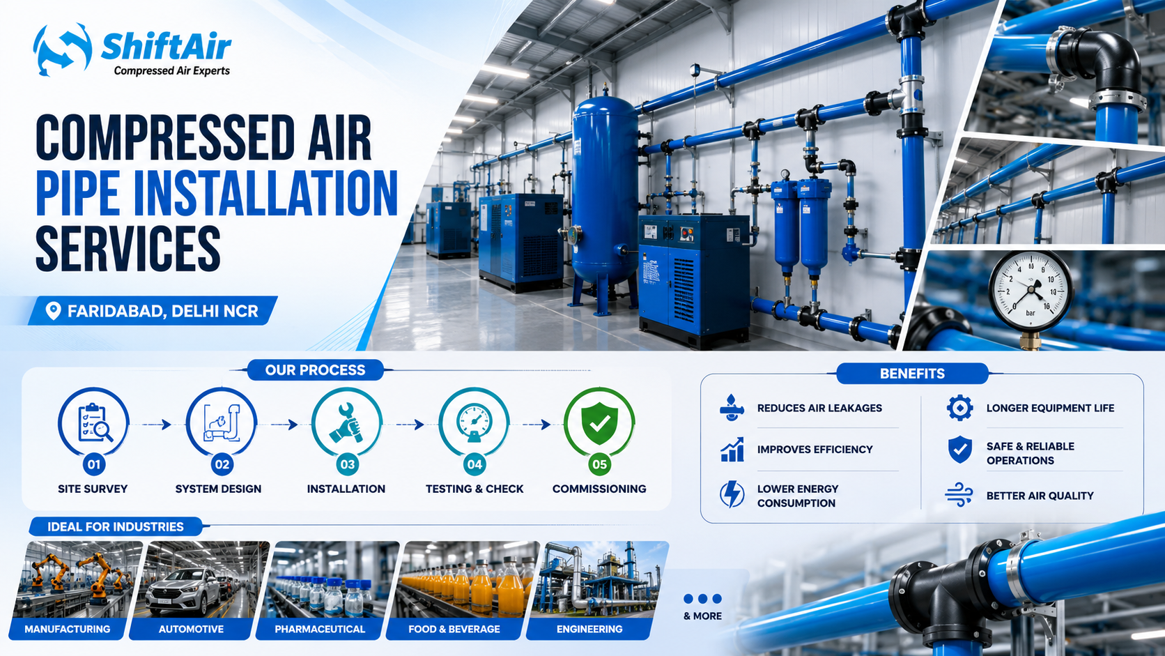
Modern factories rely on compressed air to run CNC machines, pneumatic tools, packaging lines, automation systems, and many other production processes. However, even the best air compressor can perform poorly if the piping system carrying the air is not properly designed or installed. A poorly designed, undersized, leaking, or incorrectly installed piping system can reduce the performance of the entire compressed air system. ShiftAir Transmission Pvt. Ltd. is a professional compressed air piping installation service provider in Faridabad, Delhi NCR, and other major industrial locations across India. We specialize in aluminium compressed air pipe systems, compressed air distribution networks, industrial air pipe installations, compressor piping, and pipe fittings for manufacturing facilities. Our goal is to help factories keep stable air pressure, reduce leakage, improve airflow, minimize energy inefficiency, and provide reliable compressed air pipelines for continuous production. A well-designed piping network can improve pressure stability, reduce air leakage, and lower energy consumption compared to old or poorly installed systems. These improvements support more consistent machine operation and reduce operating costs. In many plants, a new compressed air piping system can recover its cost through energy savings, reduced maintenance, and improved production reliability. Manufacturing managers can also calculate the return on investment to clearly understand the financial benefits of upgrading an existing piping network. For example, if a factory spends ₹10 lakh per year on compressed air energy costs and a new piping system reduces leakage and pressure drops by 20 percent, this could save up to ₹2 lakh annually. If the new installation costs ₹5 lakh, the simple payback period would be approximately 2.5 years. Actual savings may vary depending on plant size, operating hours, and current system condition, but most facilities experience payback within 2 to 3 years. Why Compressed Air Piping Design Is Important Factories often focus on compressor selection, capacity, pressure, motor rating, brand, and price. However, the pipe network is just as important. A properly designed piping system improves the overall efficiency of the compressed air system, whereas an improperly designed system can lead to pressure loss, leakage, higher energy consumption, and poor machine performance. Common compressed air piping problems include pressure drops, air leaks, internal rust, moisture collection, undersized pipes, too many bends, weak joints, and incorrect machine connections. These issues can cause low pressure at the point of use, frequent compressor cycling, increased energy bills, and reduced productivity. An efficient compressed air piping system supplies the required airflow and pressure to each machine. It should be easy to maintain, safe to operate, and suitable for future expansion. Professional installation requires knowledge of industrial airflow, pressure loss, pipe routing, fittings, valves, and production requirements. Compressed Air Piping Contractors in Faridabad and Delhi NCR Faridabad and Delhi NCR have many automotive units, engineering workshops, fabrication plants, packaging industries, pharmaceutical companies, food processing units, textile factories, electrical component manufacturers, and CNC job shops. These industries depend heavily on reliable compressed air for continuous production. ShiftAir serves industrial customers in Faridabad, Ballabgarh, IMT Faridabad, Gurugram, Manesar, Noida, Greater Noida, Ghaziabad, Bhiwadi, Neemrana, Kundli, Sonipat, and nearby industrial areas. As compressed air piping contractors in Faridabad and Delhi NCR, we understand the problems encountered by local factories. These include old GI pipelines, multiple compressor additions, layout changes, air leakage, and pressure drop at remote machines. We inspect the existing installation and recommend solutions based on site conditions, production requirements, and future expansion needs. For example, one automotive client faced low air pressure at remote workstations and constant leakage from an aging GI pipeline. After a complete assessment, we installed a modular aluminium piping system, optimized the routing, and upgraded the fittings. Within the first month, the customer noticed improved machine performance and a reduction in compressor load. Whether your project involves a new plant setup, production expansion, replacement of old pipelines, or conversion to aluminium compressed air piping, ShiftAir can support you from planning to commissioning. Aluminium Compressed Air Piping Systems ShiftAir provides modular aluminium compressed air piping systems for industrial applications. Aluminium piping is preferred because it is clean, lightweight, corrosion-resistant, and easy to modify. Traditional GI or MS pipes can rust over time. Internal corrosion can reduce air quality, increase pressure drop, and affect pneumatic components. Rust and moisture can damage tools, valves, cylinders, filters, and automation systems. Aluminium compressed air pipes have a smooth internal surface, better airflow, and long-term corrosion resistance. Modular systems are engineered for quick installation and easy expansion. If your industry requires clean air delivery, low maintenance, and up-to-date infrastructure, aluminium piping is a practical and budget-friendly choice. The advantages of aluminium compressed air piping include: Corrosion resistance Improved airflow due to a smooth inner surface Lower pressure drop compared to old or rough pipes Lightweight construction for easy installation Leak-resistant modular fittings Cleaner compressed air distribution Easy modification and future expansion Low maintenance Professional appearance inside the factory These features make aluminium pipes suitable for automotive plants, pharmaceutical units, food and beverage industries, electronics manufacturing, packaging lines, textile units, engineering workshops, CNC shops, and automation-based production facilities. Our Air Piping Installation Process Every compressed air piping project starts with a careful site study. Before installation, we assess the compressor room, air receiver, dryer, filter arrangement, machine layout, air consumption points, operating pressure, pipe distances, and future expansion plans. A site assessment usually takes 1 to 2 days, while a standard installation for a medium-sized factory may take 3 to 7 days, depending on the project scope. In most cases, we keep downtime for the main production lines between 4 and 8 hours, but this can vary depending on your existing system and chosen installation method. We plan the installation around your production shifts, target downtime, and isolate pipeline sections wherever possible to minimize disruption. Our team coordinates closely with your staff to complete work in phases, ensuring critical areas stay functional and that any unavoidable downtime is kept as short as possible. Based on the site survey, we prepare a practical piping layout. This includes main header routing, branch
Why Current Industries Are Switching to Modular Aluminium Piping Systems
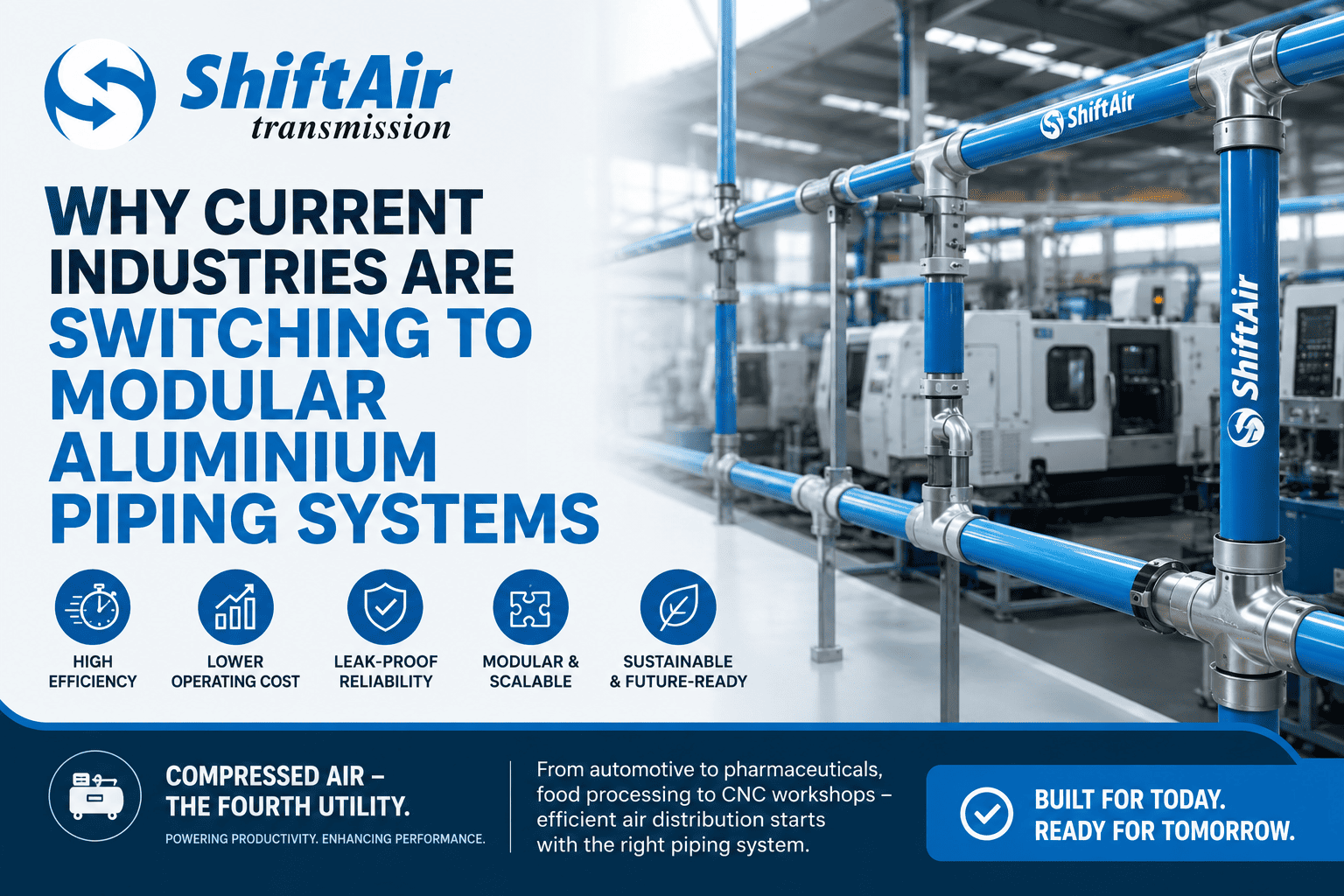
Compressed air is one of the most important utilities in modern manufacturing. Whether it is used for running pneumatic tools, automation systems, packaging lines, or CNC machinery, a reliable compressed air network is critical for smooth and efficient operations. Many companies invest heavily in high-performance air compressors but often overlook the infrastructure responsible for distributing compressed air throughout the facility. However, even the best compressor cannot operate efficiently if the piping system experiences pressure loss, air leakage, or airflow restrictions. This is why many Indian industries are switching from traditional GI and steel pipelines to aluminium compressed air piping systems, which offer improved airflow, reduced maintenance, faster installation, and significant energy savings. In fact, aluminium piping can reduce pressure drop by up to 30 per cent compared to conventional steel systems, delivering overall energy cost reductions of 15 to 25 per cent. Some facilities have reported saving 5 to 8 lakh rupees annually on electricity bills after converting to aluminium piping, making the investment quick to recover. Manufacturers striving for greater productivity and lower operating costs are increasingly adopting aluminium compressed air piping systems as a key component of modern industrial infrastructure. One often-overlooked function of a compressed air piping system is its role in overall system efficiency. Much of the discussion surrounding compressed air equipment focuses on compressors, dryers, and filtration systems. However, the piping network is equally important in determining overall system performance. Think of the piping system as a highway that carries compressed air from the compressor room to various production areas. If that highway is poorly designed, congested, or damaged, the entire system becomes inefficient. Some of the common problems caused by poorly designed piping networks include: Pressure loss Air leaks Non-uniform flow distribution Increased compressor load Higher electricity consumption These issues directly impact productivity, production efficiency, and operating costs. A well-designed compressed air distribution system ensures that every machine receives the air pressure it requires while minimizing energy loss throughout the network. Why Traditional Steel and GI Pipes Are Becoming Obsolete GI and steel pipes have been widely used in industrial compressed air systems for decades. While they have served their purpose, modern manufacturing environments demand greater efficiency, reliability, and flexibility. One of the biggest disadvantages of steel pipelines is internal corrosion. Rust buildup inside the pipe restricts airflow and increases pressure losses. The rough internal surface creates additional resistance, forcing compressors to work harder to maintain the desired operating pressure. Rust contamination can also negatively affect air quality, which is a major concern for industries such as pharmaceuticals, food processing, electronics manufacturing, and precision engineering. In addition, steel pipelines require welding, threading, and extensive maintenance, making future modifications expensive and time-consuming. These limitations have encouraged industries to seek more efficient alternatives. Aluminium is transforming industrial air distribution across India by providing a competitive advantage that traditional piping systems cannot match. Aluminium has become one of the most effective materials for compressed air distribution systems. Unlike steel, aluminium does not rust internally, keeping the airflow path clean and smooth throughout the system’s lifespan. This results in lower pressure drops, higher efficiency, and improved equipment performance. Another major advantage is its lightweight construction. Aluminium pipes are significantly lighter than steel pipes, making them easier to transport, handle, and install. Most aluminium piping systems utilize simple mechanical fittings such as push-to-connect or clamp joints, eliminating the need for skilled welders or specialized tools. Typical installation involves measuring and cutting the pipe, assembling sections using connectors, and securing the system with basic supports. This straightforward process allows maintenance teams to complete installations, modifications, and future expansions quickly and efficiently. For industrial facilities, these advantages translate into: Faster installation Reduced labour costs Lower structural loading Easier future expansion These practical benefits, combined with energy savings and reduced maintenance requirements, make aluminium piping an attractive solution for manufacturers seeking greater efficiency. How Pressure Drop Affects Energy Costs Pressure losses within compressed air networks often result in significant energy waste that goes unnoticed. Pressure drop refers to the loss of compressed air pressure as it travels through the piping system. Common causes include: Rusted pipes Poor network design Excessive bends and curves Undersized piping Air leakage Many facilities compensate for pressure loss by increasing compressor pressure settings. While this may solve the immediate problem, it also increases energy consumption and operating expenses. To avoid unnecessary costs and maintain optimal efficiency, facilities should regularly monitor system pressure at key points throughout the network. Periodic pressure audits using portable gauges or digital monitoring tools can quickly identify hidden losses before they result in higher energy bills. Installing permanent pressure monitoring devices allows continuous tracking, enabling maintenance teams to detect and address issues before they become major problems. A well-designed aluminium piping system promotes smooth airflow and minimizes pressure drops, improving compressor efficiency and reducing electricity consumption. Significance of Leak-Free Air Distribution Air leakage is one of the most common causes of energy loss in industrial facilities. Even small leaks can accumulate over time, leading to substantial energy waste. Many plants lose a significant portion of their compressed air due to leaking joints, damaged fittings, and aging pipeline infrastructure. Modern aluminium piping systems use advanced connection technologies specifically engineered to minimize leaks, improving system reliability and reducing wasted energy. Reducing air loss helps industries: Increase compressor efficiency Lower electricity bills Improve equipment performance Reduce maintenance requirements Preventing leaks is one of the simplest and most effective ways to maximize the return on investment from a compressed air system. How Modular Piping Systems Support Future Growth Industrial plants are constantly evolving. New production lines, additional machinery, and process upgrades often require changes to the compressed air network. With traditional steel piping systems, these modifications can be expensive and disruptive. Aluminium piping systems are purpose-built for flexibility. Their modular design allows companies to expand, relocate, or modify air distribution networks quickly while minimizing downtime. For example, a leading auto component manufacturer in Pune recently upgraded from steel to aluminium piping to support a new production
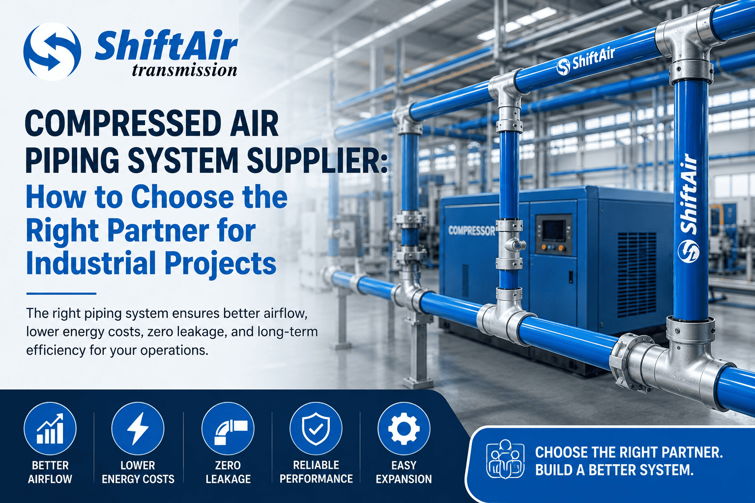
Compressed Air Piping System Supplier: How to Choose the Right Partner for Industrial Projects
Compressed air is sometimes called the fourth service in modern manufacturing because it powers essential equipment in many industries, including automotive, pharmaceuticals, food processing, textiles, electronics, and CNC machining. However, the system’s efficiency relies not just on the compressor but also on the quality of the piping network that distributes air throughout the facility. Buying a good air compressor is important, but the piping system that carries the air throughout the facility is equally important. If the piping system is not properly designed or installed, it can cause air leaks, pressure drops, increased energy costs, and lower overall productivity. Choosing the right supplier is not only about buying pipes and fittings. It means picking a partner who can offer engineering know-how, help with installation, optimise airflow, and ensure the system runs reliably over time. To ensure a partner brings both products and expertise, plant managers must follow key evaluation steps: Review the supplier’s previous project case studies, ask for references from other industrial clients, and consider organising a site visit to observe installations in action. Ask for detailed proposals and compare how each supplier approaches design, materials, and after-sales service. These actions help ensure you select an established partner for reliable, durable performance. When evaluating suppliers, it’s important to be vigilant for any potential warning signs. Warning signs may include reluctance or inability to provide references, vague or generic project proposals, insufficient documentation of previous work, poor communication during the inquiry process, or inconsistent responses to technical questions. If a supplier does not offer site visits or avoids providing detailed system designs, these may also indicate a lack of experience or reliability. Identifying such issues early helps you avoid unreliable partners and make confident decisions. Why the Right Compressed Air Piping System Supplier Matters A compressed air system works as a complete network. Every pipe, fitting, valve, connector, and support structure affects how well the system performs. An experienced supplier ensures correct pipeline sizing, high-performance airflow design, lower pressure drop, reduced energy use, and future expansion options. Poorly designed systems may require compressors to operate at higher pressures to compensate for airflow losses. This can increase electricity costs and cause extra wear on equipment. Hidden Costs of Poor Compressed Air Pipeline Design Many factories still use old GI or MS piping systems because they cost less at first. However, these systems often lead to hidden costs later. Pressure Drop Pressure drop happens when compressed air loses pressure as it moves through the pipes. This can be caused by rough pipe surfaces, corrosion, too many bends, incorrect pipe sizes, or long distribution routes. Even slight pressure drops cause compressors to use more energy to maintain the required pressure. Air Leakage Leaks are a major cause of wasted energy in industrial compressed air systems. Leaks often occur at threaded joints, corroded sections, poor fittings, and old pipeline infrastructure. A professional compressed air pipe manufacturer focuses on leak prevention through improved connection technology and optimised system designs. Maintenance Expenses Traditional steel pipelines often require repeated repairs, rust removal, joint replacements, and, at times, production shutdowns. These maintenance tasks raise operating costs and lower plant productivity. What to Look for in an Industrial Air Compressor Piping Solutions Provider Not all suppliers have the same level of expertise. Before you choose a partner, keep these factors in mind. Engineering Capability A reliable supplier should offer airflow calculations, pipe sizing advice, pressure drop analysis, and support for network optimisation. Engineering support ensures the system works efficiently from the start. Installation Expertise Many projects fail when installation quality is ignored. Choose suppliers who offer site surveys, installation planning, professional commissioning, and system testing. Experienced suppliers can also schedule installations during planned shutdowns or off-peak hours to minimise plant downtime and prevent disruptions during ongoing production. Proper installation greatly improves extended reliability. Product Quality Industrial buyers should evaluate material quality (such as strength and durability), corrosion resistance (ability to resist rust and corrosion), pressure ratings (maximum pressure a pipe can safely withstand), and connection technology (how pipes and fittings are joined) to improve system performance and service life. Future Expansion Support Manufacturing plants often grow and expand over time. Systems should allow for: Additional machine connections New production lines Future capacity increases without major disruptions to current operations. Why Aluminium Compressed Air Piping Systems Are Replacing Traditional GI Pipes Industries across India are increasingly choosing aluminium compressed air piping systems because they offer numerous operational advantages. Corrosion-Free Performance Unlike GI pipes, aluminium does not rust internally. This helps keep airflow clean, improves air quality, and lowers the risk of contamination, which is especially important for pharmaceutical and food processing applications. Improved Airflow Efficiency Smooth internal pipe surfaces allow compressed air to flow through the system with less resistance. This reduces pressure drop, which means the compressor does not have to work as hard to deliver the required air pressure. This sustains uninterrupted airflow, improves efficiency, and lowers energy consumption. Faster Installation Modern modular aluminium systems can be installed much faster than traditional steel piping networks. This helps reduce project schedules, installation labour, and production downtime. Lower Lifetime Cost While aluminium systems may cost more initially, their lower maintenance requirements, energy savings, and reduced downtime often make them more advantageous in the long term. In many industrial applications, the investment in aluminium compressed air piping typically pays for itself within 18–36 months, thanks to lower energy costs and reduced maintenance. For example, a medium-sized facility switching from GI to aluminium piping can often recoup the added upfront cost in less than two years due to significant reductions in air leaks, pressure drop, and repair expenses. This quick payback makes aluminium pipes a practical and cost-effective choice for modern plants. Industries That Depend on Efficient Compressed Air Distribution Systems A well-designed compressed air distribution system is important for many industries. Automotive Manufacturing Compressed air powers robotic systems, paint booths, assembly tools, and material-handling equipment. Pharmaceutical Industry Reliable compressed air is required for packaging, production equipment, and clean manufacturing