
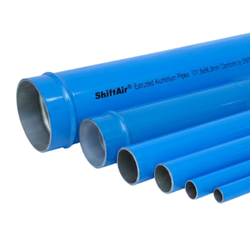
A compressed air piping system may look simple on a drawing: a compressor, a main line, several branches and connections to production equipment. In practice, small installation decisions can have a major effect on pressure stability, energy consumption, air quality and long-term maintenance.
Pipes that are too small, poorly routed or incorrectly supported may restrict airflow and increase pressure drop. Inadequate drainage can send moisture towards tools and machines. Weak connections may create recurring leaks, while a layout with no isolation strategy can force a factory to shut down an entire compressed air network for a minor repair.
These problems are often discovered only after production begins. By that stage, correcting the system may require additional fittings, replacement piping, production downtime or an unnecessary increase in compressor pressure.
The following ten compressed air piping installation mistakes should be addressed during the design and installation stages rather than after commissioning.
Why Proper Compressed Air Piping Installation Matters
The compressor is only one part of an industrial compressed air system. Once the air leaves the compressor room, the piping network must deliver the required airflow and pressure to every production area.
A factory may install a correctly sized compressor and still experience low pressure at machines if the distribution system is undersized, restricted or poorly arranged. Operators may respond by increasing the compressor discharge pressure. That may improve pressure at the final machine temporarily, but it can also increase electricity consumption, leakage and stress on system components.
A properly planned compressed air distribution system should support five basic objectives:
- Deliver the required airflow to each point of use
- Maintain stable pressure during changing production demand
- Minimise pressure drop and leakage
- Control moisture and contamination
- Allow safe maintenance and future expansion
Installation Should Be Based on Demand, Not Compressor Outlet Size
The connection size on the compressor should not automatically determine the size of the entire distribution network. Pipe diameter should be selected according to airflow, operating pressure, total pipe length, acceptable pressure drop, network configuration and expected future demand.
Choosing the Wrong Pipe Material
Selecting piping only according to its initial purchase price can lead to higher operating and maintenance costs over the system’s lifetime.
Traditional threaded metal piping may be familiar to installers, but internal corrosion, scaling and rough surfaces can increase resistance to airflow. Threaded joints may also become recurring leak points, particularly in areas exposed to vibration or repeated production changes.
Plastic materials that are not specifically approved for compressed air service can create serious safety risks. A material suitable for water is not automatically suitable for compressed gas. Compressed air stores energy, and an unsuitable pipe can fail differently from a water pipe.
The selected material should be rated for the intended operating pressure and temperature and should be compatible with the compressor lubricant, environmental conditions and required air quality.
Better approach: Compare materials based on pressure rating, corrosion resistance, internal surface condition, leak risk, installation method, safety, maintenance requirements and future modification costs—not only the initial price per metre.
Installing Undersized Compressed Air Pipes
Undersized piping is one of the most common causes of excessive pressure drop. A smaller pipe forces compressed air to travel at a higher velocity. This increases friction and makes pressure losses worse, especially across long distances and during periods of peak demand.
A system may appear to perform correctly when only a few machines are operating. The problem becomes visible when multiple production lines demand air at the same time.
Common symptoms of undersized piping include:
- Low pressure at machines far from the compressor room
- Pressure fluctuations when high-demand equipment starts
- Slow pneumatic cylinder movement
- Reduced pneumatic tool performance
- Operators increasing regulator or compressor pressure
- Production interruptions during peak demand
Pipe sizing should consider both the current airflow and reasonable future growth. Choosing a pipe that can only support today’s average demand may require an expensive replacement when new machines are added.
Better approach: Size the main and branch lines using measured or calculated airflow, total equivalent length, working pressure and an acceptable pressure-drop target. Include expected expansion rather than designing only for current demand.
Using Too Many Bends and Restrictive Fittings
Every bend, tee, reducer, valve and connection adds resistance to airflow. A long-radius bend generally creates less resistance than a sharp change in direction, while a poorly selected valve may create a significant restriction even when fully open.
The actual resistance of a piping network therefore depends on more than its measured straight-line length. Designers use the concept of equivalent length to account for the pressure loss created by fittings and directional changes.
An installation with frequent turns may behave like a much longer system than it appears on a floor plan. This is particularly important when pipes are routed around cable trays, structural columns, storage areas or existing equipment without an organised layout.
Sudden reductions in diameter can also create bottlenecks. A properly sized main line provides limited benefit if airflow must pass through a restrictive connector, undersized valve or small flexible hose before reaching the machine.
Better approach: Use direct, organised routes with gradual direction changes. Minimise unnecessary fittings and check the internal bore of valves, connectors, hoses and point-of-use components.
Designing an Inefficient Compressed Air Pipe Layout
A single dead-end pipe may be suitable for a small installation with limited and predictable demand. In a larger factory, a ring-main or looped system often provides better pressure stability.
In a ring layout, air can reach a demand point from more than one direction. This shares the airflow across different sections of the network and can reduce the pressure drop experienced at distant machines.
A poor layout may also place high-demand machines at the end of a long, small-diameter branch. When that machine starts, it can pull down pressure throughout the branch and affect other equipment.
Long flexible hoses should not be used as a substitute for permanent distribution piping. Small-bore coiled hoses and restrictive quick couplings can create a substantial pressure loss between the branch line and the tool.
Common Layout Problems
- Long dead-end mains serving multiple production areas
- High-demand equipment connected through small branches
- Production machines supplied through excessive hose lengths
- No separation between stable process air and intermittent high demand
- Unnecessary pipe crossings and directional changes
- No convenient route for future extension
Better approach: Consider a ring main for factories with multiple production areas. Connect high-demand equipment through appropriately sized branches and evaluate whether local receivers are required for short, intermittent demand peaks.
Ignoring Pressure-Drop Calculations
Pressure drop is the difference between the pressure available at the compressor or air-treatment outlet and the pressure reaching the point of use.
Some pressure loss is unavoidable, but excessive pressure drop means the compressor must operate at a higher pressure to deliver the minimum required pressure at the machine. Producing air at a higher pressure requires more energy and may increase leakage throughout the network.
Pressure drop can occur across:
- Undersized main and branch piping
- Long pipe runs
- Air dryers and filters
- Partially closed or restrictive valves
- Excessive bends and fittings
- Small regulators and lubricators
- Quick couplings
- Flexible hoses
- Blocked or poorly maintained components
Checking only the compressor discharge pressure can hide the real problem. Pressure should be measured at critical points under normal production conditions and during peak demand.
Better approach: Calculate pressure loss during the design stage and confirm it with pressure measurements after installation. Evaluate the complete air path, including dryers, filters, valves, hoses and point-of-use equipment.
Poor Moisture Drainage and Incorrect Pipe Slope
Compressing air concentrates water vapour. After the air cools, moisture can condense inside the system. Although aftercoolers, separators and dryers remove much of this moisture, the distribution network must still be designed to prevent remaining condensate from reaching production equipment.
A horizontal pipe installed without a controlled slope can allow water to collect in low points. Sudden airflow changes may carry this accumulated moisture towards machines, tools and sensitive processes.
Branch connections taken from the bottom of a wet main may collect water directly from the pipe. Poorly located drains can also become difficult to inspect and maintain.
Moisture-related problems may include:
- Corrosion inside tools and equipment
- Contaminated products or surfaces
- Damage to pneumatic components
- Blocked or frozen lines in cold environments
- Reduced filter life
- Unexpected maintenance requirements
Better approach: Plan controlled pipe slopes and drainage points according to the system design. Where appropriate, take branch drops from the top of the main and use drop legs or moisture-separation arrangements before the point of use.
Using Too Few Isolation Valves
A compressed air distribution system needs to be maintained, modified and expanded. Without properly located isolation valves, a minor repair may require depressurising the entire factory network.
This increases production disruption and may cause maintenance teams to postpone necessary work. A leaking hose, faulty drain or damaged branch may continue wasting energy simply because isolating the section is too difficult.
Isolation is also useful for production areas that do not operate continuously. A department that is closed at night or during weekends should not necessarily remain pressurised if it contains hoses, tools and connections that may leak.
Useful isolation points may include:
- Individual production departments
- High-demand machines
- Future expansion branches
- Outdoor or seasonal production areas
- Major ring-main sections
- Maintenance-intensive equipment
Better approach: Install accessible, clearly labelled isolation valves at strategic points. Design the network so maintenance can be completed with the smallest practical area depressurised.
Incorrect Pipe Supports and Mounting
Compressed air pipes need appropriate support to remain aligned and secure. Incorrect support spacing can allow sagging, movement, vibration and stress at joints.
Overly rigid mounting can also create problems if the installation does not accommodate thermal expansion and contraction. Temperature changes occur as compressed air leaves the compressor room, passes through different environments and responds to changing production conditions.
Pipes should not be supported by machine connections, air-treatment equipment or temporary structures. They should also be protected from forklifts, cranes, moving machinery and other potential impact hazards.
Unsupported drops and long hose assemblies can transfer mechanical stress to fittings. Over time, this movement may contribute to leaks or connection failure.
Better approach: Follow the piping manufacturer’s support-spacing and installation instructions. Use suitable brackets, maintain alignment, allow for movement where required and protect vulnerable pipe sections from impact.
Failing to Plan for Future Expansion
Industrial compressed air demand rarely remains unchanged. Factories add production lines, relocate machines, expand departments and introduce new pneumatic processes.
A network designed only for today’s equipment may become restrictive after expansion. The factory may then add unplanned branches, temporary hoses and repeated reductions in pipe size.
These additions can gradually transform an organised distribution system into a complex network with excessive fittings, poor isolation and unpredictable pressure drop.
Future planning should consider:
- Expected production growth
- Possible machine relocations
- Additional compressor capacity
- Space for new dryers and filters
- Future ring-main extensions
- Convenient connection points
- Isolation of unused future branches
Better approach: Allow reasonable spare capacity in the main distribution system and install planned, isolated connection points. A modular compressed air piping system can simplify later extensions and production-layout changes.
Skipping Leak Testing and Commissioning Checks
A newly installed compressed air network should not be assumed to be leak-free. Leaks may occur at incorrectly assembled fittings, valves, drains, hoses, threaded adapters or machine connections.
If the system is commissioned without a structured inspection, these leaks can remain unnoticed for years. The factory then pays to compress air that never reaches a productive application.
Commissioning should confirm more than leak tightness. It should also verify pressure, airflow, drainage, valve operation, support condition and the performance of critical points of use.
Commissioning checks should include:
- Inspection of all joints and fittings
- Leak testing according to approved procedures
- Pressure measurement at critical points
- Confirmation of valve accessibility and labels
- Inspection of pipe supports and alignment
- Testing of condensate drains
- Verification of regulators, filters and hoses
- Confirmation that unused branches are isolated
- Recording baseline pressure and airflow data
Compressed Air Testing Requires Safe Procedures
Compressed gas stores significant energy. Pressure testing, commissioning and maintenance must be completed by competent personnel following the pipe manufacturer’s instructions, applicable standards and the factory’s established safety procedures.
Better approach: Complete a documented commissioning process before production begins. Correct identified defects, retest repaired areas and retain the final results as a baseline for preventive maintenance.
How Installation Mistakes Affect Factory Performance
| Installation Problem | Immediate Effect | Long-Term Business Impact |
|---|---|---|
| Undersized piping | High air velocity and pressure drop | Higher compressor pressure, increased electricity use and production problems |
| Excessive bends and restrictions | Reduced airflow | Unstable pressure and poor machine performance |
| Poor moisture drainage | Water reaches branches and equipment | Corrosion, maintenance and product-quality risks |
| Too few isolation valves | Large areas must be depressurised | Longer maintenance shutdowns and delayed leak repairs |
| Incorrect supports | Movement, sagging and joint stress | Recurring leaks and mechanical damage |
| No expansion planning | Temporary or unorganised connections | Increasing pressure drop and expensive future modifications |
| No commissioning test | Installation defects remain unidentified | Continuous air leakage and unreliable system performance |
Compressed Air Piping Installation Checklist
Use the following checklist during the design, installation and commissioning stages:
- Confirm the current and future compressed air demand.
- Record the required pressure at critical machines.
- Select piping approved for compressed air service.
- Size the main and branch lines using airflow and pressure-drop calculations.
- Consider a ring-main layout for larger production facilities.
- Minimise unnecessary bends, restrictions and diameter reductions.
- Check the bore size of valves, hoses and quick couplings.
- Plan suitable drainage points and pipe slopes.
- Install accessible isolation valves for departments and machines.
- Use supports and brackets according to manufacturer requirements.
- Protect pipes from impact and mechanical damage.
- Provide isolated connection points for future expansion.
- Label valves, branches and production areas clearly.
- Leak test the complete installation before commissioning.
- Measure pressure at the compressor room and critical points of use.
- Record baseline pressure, airflow and compressor performance.
How Aluminium Piping Addresses Common Installation Problems
Modular aluminium compressed air piping is increasingly used in industrial distribution networks because it addresses several limitations associated with older traditional piping systems.
Aluminium has a smooth internal surface and does not suffer from internal rust in the same way as untreated iron-based piping. This helps maintain cleaner airflow and consistent internal conditions over time.
Modular fittings can also reduce the amount of threading, welding and on-site fabrication required during installation. This may simplify production-line extensions and reduce the disruption associated with future modifications.
Potential benefits of a properly designed aluminium piping system include:
- Corrosion resistance
- Smooth internal airflow path
- Lightweight handling
- Organised installation
- Faster network modification
- Reduced dependence on threaded joints
- Suitability for modular factory expansion
- Cleaner appearance and easier identification
Material selection alone does not guarantee an efficient compressed air system. Aluminium pipes must still be correctly sized, supported, routed, drained and tested.
Learn more about selecting a suitable partner in ShiftAir’s guide to choosing a compressed air piping system supplier .
You can also review the benefits of aluminium compressed air pipes for industrial air distribution.
Build the Compressed Air Network Around Factory Performance
A compressed air piping installation should not be treated as a simple exercise in connecting the compressor to production equipment. The network has a direct influence on pressure stability, electricity consumption, moisture control, maintenance accessibility and future factory expansion.
The most expensive installation mistakes often begin with seemingly small decisions: selecting a pipe that is slightly too small, adding unnecessary bends, using a long flexible hose, omitting an isolation valve or failing to test the final installation.
Correcting these problems after commissioning can cost significantly more than addressing them during the design stage. A well-planned system should combine correct pipe sizing, efficient routing, reliable drainage, strategic isolation, proper support and documented commissioning.
Factories planning a new network should evaluate the complete compressed air path—from the compressor and air treatment equipment to the furthest point of use—rather than considering the piping as a separate component.
Planning a New Compressed Air Piping Installation?
ShiftAir Transmission supplies modular aluminium compressed air pipes, fittings, valves and accessories for industrial compressed air distribution systems.
Share your compressor capacity, working pressure, approximate pipe length, production layout and airflow requirements with the ShiftAir team to begin evaluating your piping network.
Discuss Your Piping ProjectFrequently Asked Questions
What Is the Best Material for Compressed Air Piping?
The best material depends on the system pressure, air quality, environment, installation requirements and budget. Modular aluminium piping is widely used in industrial compressed air networks because it is corrosion-resistant, lightweight, clean internally and easier to modify than many traditional threaded systems.
How Much Pressure Drop Is Acceptable in a Compressed Air Piping System?
Allowable pressure drop depends on the process, but the system should deliver the required pressure at the most distant or critical point of use without forcing the compressor to operate at an unnecessarily high discharge pressure.
Pressure-drop targets should consider the complete system, including piping, dryers, filters, valves, hoses, couplings and regulators.
Should Compressed Air Pipes Be Installed With a Slope?
Where moisture may collect, horizontal mains should normally be installed with a controlled slope towards suitable drainage points. The exact arrangement depends on the air-treatment system, piping layout, operating conditions and facility requirements.
Why Is a Ring-Main Layout Recommended for Factories?
A ring-main layout allows compressed air to reach demand points from more than one direction. This can improve pressure stability, reduce pressure drop and allow sections of the network to be isolated more conveniently for maintenance.
Can Poor Pipe Installation Increase Compressor Electricity Consumption?
Yes. Undersized piping, excessive bends, restrictive fittings, blocked filters and leaks increase pressure losses and artificial demand. Factories may compensate by raising compressor pressure, which can increase electricity consumption.
When Should Compressed Air Piping Be Leak Tested?
The complete system should be tested before commissioning, after significant modifications and as part of regular preventive maintenance. Testing must follow the piping manufacturer’s instructions and the facility’s safety procedures.