
Compressed air pipe sizing must be engineered from the volumetric flow rate (CFM/FAD), working pressure, total equivalent pipeline length, and allowable line pressure drop. Never rely on the compressor discharge port size alone—an air compressor outlet does not determine the correct distribution pipe diameter. An undersized main distribution header creates chronic pressure fluctuations, increases compressor energy expenditure, and chokes pneumatic tool performance across your facility.
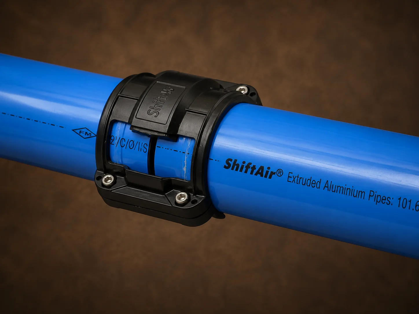
Engineering Best Practice: While a generic compressed air pipe size chart offers a quick starting point, precise pneumatic piping design requires calculating friction loss against the true internal diameter (ID) and absolute surface roughness (k-value) of the pipe material. Modular aluminum piping systems feature a calibrated bore and mirror-smooth inner walls that drastically lower hydraulic friction compared to threaded galvanized iron (GI) piping.
5 Key Inputs for Compressed Air Pipe Sizing Calculations
Accurate compressed air distribution system design demands five interdependent technical variables:
| Design Parameter | Required Specification | Impact on Piping Performance |
|---|---|---|
| Volumetric Flow Rate | Peak air consumption in CFM, L/s, or m³/hr across each piping segment | Determines internal pipe cross-sectional area; undersizing causes flow choking and excessive air velocity |
| Operating Pressure | Bar(g) / PSI(g) working gauge pressure, converted to absolute pressure bar(a) | Higher working pressure compresses air density, reducing volumetric velocity and internal frictional resistance |
| Equivalent Length | Physical pipe run plus the hydrodynamic resistance of all elbows, tees, and valves | Frictional drag accumulates with length, compounding total terminal pressure drop |
| Target Pressure Drop (ΔP) | Permissible pressure differential between compressor outlet and critical end-use points | Sets the baseline internal diameter; lower allowable ΔP requires larger pipe cross-sections |
| Network Architecture | Loop/ring main vs. dead-end branch layout, plus diversity and future machine growth | Dictates directional airflow distribution, velocity distribution, and branch isolation requirements |
Flow Rates Explained: CFM, SCFM, ACFM, and Compressor FAD
Airflow volume cannot be measured reliably without defining reference temperature and ambient atmospheric pressure. Air compressor capacity is rated in Free Air Delivery (FAD) per ISO 1217 standards—the actual volume of ambient air aspirated, compressed, and delivered to the receiver tank.
When computing pipe diameter for pneumatic systems, avoid these common flow calculation errors:
- Conflating compressor rated FAD at standard suction conditions with pneumatic tool consumption stated at point-of-use working pressure.
- Confusing Standard Cubic Feet per Minute (SCFM) with Actual Cubic Feet per Minute (ACFM) flowing inside pressurized pipes.
- Summing all tool nameplate CFM ratings together without calculating a realistic plant diversity coefficient (duty cycle).
- Using general site flow measurements without compensating for transient peak demands.
Segment-by-Segment Airflow Sizing
The central compressor-room manifold and main utility header must carry the plant’s maximum simultaneous coincident demand. Departmental distribution branches need only carry regional equipment load, and terminal drop legs are sized strictly for individual machine peak draw. Never apply uniform sizing across the entire network.
System Working Pressure & Hydraulic Resistance
Compressed air calculations rely on absolute pressure (bar(a) or psia) rather than gauge pressure (bar(g) or psig):
At higher system pressures, air occupies less volume for an equivalent mass flow, resulting in reduced linear flow velocity and lower friction losses. However, running a compressor at artificially elevated discharge pressure simply to push air through undersized, restrictive piping is economically inefficient: every 1 bar (14.5 PSI) increase in compressor discharge pressure raises plant electrical power consumption by approximately 7% to 10%. The correct strategy is always to optimize pipeline bore diameter rather than overworking the compressor motor.
Actual Physical Length vs. Equivalent Pipeline Length
A compressed air line is never a purely straight run. Directional changes, tee junctions, reducers, inline moisture separators, and isolation valves impose localized turbulence and kinetic energy losses. Equivalent length models each pneumatic fitting as an additional equivalent segment of straight pipe.
In standard factory distribution networks, fittings and bends routinely account for 20% to 40% of overall pipeline resistance. A straight physical route measuring 100 meters can easily equate to 135 meters of equivalent length once elbows, bypass valves, and union fittings are factored in. Smooth-flow aluminum push-fit fittings maintain full-bore passage and induce significantly lower localized turbulence than threaded, rough-cast iron fittings.
Establishing an Allowable Pressure Drop Budget (ΔP)
For high-efficiency manufacturing plants, world-class engineering standards dictate that total pressure drop across the entire fixed piping network should not exceed 0.1 bar (1.45 PSI / ~1.5% of total system pressure) between the air receiver tank and the furthest point of consumption.
An optimal industrial compressed air pressure budget is allocated systematically:
- Compressor Room Treatment (Dryers, Pre/After Filters): 0.15 to 0.25 bar ΔP
- Main Plant Header or Closed-Loop Ring: ≤ 0.05 bar (0.7 PSI) ΔP
- Sub-Distribution Sub-Headers and Branches: ≤ 0.03 bar (0.4 PSI) ΔP
- Point-of-Use Drop Lines: ≤ 0.02 bar (0.3 PSI) ΔP
- Final Machine Hookups (FRL unit, quick-connect couplers, flexible air hose): ≤ 0.10 bar ΔP
Step-by-Step Compressed Air Pipe Sizing Process
Piping Network Architecture: Headers, Branches, and Drops
| Piping Tier | Design Airflow Capacity | Recommended Air Velocity | Common Design Error |
|---|---|---|---|
| Compressor Header | 100% of maximum simultaneous compressor delivery | 4 – 6 m/s (13 – 20 ft/s) | Sizing the header identical to the compressor outlet port thread |
| Primary Ring Main | Coincident flow across interconnected distribution loops | 6 – 8 m/s (20 – 26 ft/s) | Assuming flow always splits 50/50 through both sides of the loop |
| Zonal Branch Lines | Coincident peak demand of machines in that production bay | 6 – 10 m/s (20 – 33 ft/s) | Summing tool nameplate CFM without verifying machine duty cycles |
| Point-of-Use Machine Drops | Peak intermittent demand of the dedicated machine | 10 – 15 m/s (33 – 50 ft/s) | Undersizing vertical drops based on average rather than peak surge CFM |
| Terminal Hose & Couplings | Immediate instantaneous machine draw at operating pressure | ≤ 15 m/s (50 ft/s) | Installing miniature restrictive push-in fittings or coiled hoses |
Why Closed-Loop Ring Mains Outperform Dead-End Branches
A closed-loop ring main (dual-feed loop) encircles the production perimeter, allowing compressed air to travel toward demand points from two directions simultaneously. This parallel flow architecture effectively halves the volumetric flow rate passing through any single branch, cutting velocity and drastically decreasing frictional pressure drop.
In addition to maintaining balanced pressure during high-demand bursts, a looped system enables isolation of specific production bays for maintenance using bypass ball valves without interrupting plant operations. For detailed engineering trade-offs, explore our comprehensive ring main vs branch line compressed air piping analysis.
Worked Industrial Sizing Example: Factory Expansion
Consider a plant adding a production wing with three production units operating at 7 bar(g) (101.5 PSI) over a route of 80 meters with 6 elbows and 2 ball valves:
| Machine Station | Free Air Demand | Duty Cycle / Pattern | Design Flow Consideration |
|---|---|---|---|
| Station A (CNC Milling) | 120 CFM (204 m³/h) | Continuous (100%) | Base continuous load |
| Station B (Pneumatic Press) | 80 CFM (136 m³/h) | Intermittent (40%) | Cyclic load with sharp 80 CFM peaks |
| Station C (Packaging Line) | 60 CFM (102 m³/h) | Intermittent (30%) | Occasional coincident firing with Press |
Design Calculation: Coincident peak demand with simultaneous cycling requires sizing the branch for approximately 220 CFM. A 1″ (25mm ID) pipe over this distance would create excessive pressure loss (> 0.4 bar) and air speeds exceeding 14 m/s, causing pressure fluctuations at Station A during Station B’s stroke. Specifying a 40mm (1-1/2″) aluminum pipe drops velocity to an efficient 5.8 m/s and keeps the total line pressure loss under 0.06 bar (0.87 PSI).
To verify precise friction loss and pipe wall resistance for your facility, use the ShiftAir compressed air pressure drop calculator.
Internal Bore Diameter (ID) vs. Nominal Pipe Size (NPS)
Piping systems are frequently misidentified by nominal external trade names. A 1-inch Schedule 40 steel pipe, a 1-inch Schedule 80 pipe, a copper tube, and an engineered modular aluminum pipe do not share identical internal diameters. Because hydraulic resistance varies inversely to the fifth power of the pipe diameter ($ΔP \propto 1/D^5$), a tiny reduction in internal bore creates an exponential spike in pressure loss.
Calibrated modular aluminum pipes maintain uniform internal dimensions, zero scale buildup, and a smooth extruded surface that remains corrosion-free over decades of service, preserving original pressure efficiency.
Sizing for Future Plant Expansion Without Capital Waste
Oversizing drop pipes for hypothetical future equipment wastes capital and increases system volume unnecessarily. However, undersizing the primary compressor header requires costly shutdowns when production lines expand. The correct engineering balance includes:
- Designing the primary ring main and headers with 25% to 40% spare flow capacity based on 3- to 5-year capital equipment roadmaps.
- Installing modular drop tees and isolation valves at modular intervals along the main header to allow new equipment hookups without system depressurization.
- Documenting planned pneumatic equipment, anticipated shifts, and automated actuator additions before finalizing pipe diameters.
11 Costly Compressed Air Pipe Sizing Mistakes
- Matching Pipe Diameter to Compressor Outlet: Discharge ports are engineered for localized connection, not long-distance line transmission.
- Sizing by Compressor Motor Horsepower (HP): HP does not dictate pipe length, system geometry, or localized pressure loss.
- Neglecting Equivalent Length of Fittings: Overlooking bends, check valves, and elbows leads to severe unaccounted pressure drop.
- Ignoring Air Flow Velocity: Speeds above 10 m/s in headers scour pipe walls, carry condensed water droplets, and create severe dynamic head loss.
- Treating Average Consumption as Peak Demand: Short, heavy pneumatic surges cause severe local starvation if pipes are sized solely for averages.
- Confusing Gauge with Absolute Pressure: Miscalculating density equations leads to significantly undersized pipe selections.
- Relying on Restrictive Hoses & Couplers: Bottlenecking a high-flow 40mm header into a 1/4″ quick-disconnect fitting starves tools right at the spindle.
- Disregarding Air Treatment Delta-P: Failing to account for pressure drops across refrigerated dryers, desiccant beds, and coalescing filters.
- Assuming Symmetric 50/50 Ring Main Flow: Unequal branch draws pull unbalanced flow volumes around loop headers.
- Increasing Compressor Setpoint as a Fix: Cranking system pressure to overcome line friction wastes significant electrical energy without curing flow restrictions.
- Installing Corrosive Carbon Steel / GI Piping: Internal rust, pitting, and scale increase surface roughness over time, multiplying pressure loss and contaminating valves.
For more plant design insights, review our guide to common compressed air piping installation mistakes.
Frequently Asked Questions
What size pipe do I need for a 100 CFM air compressor?
A 100 CFM system cannot be sized on flow alone. For a short run under 30 meters at 7 bar(g), a 25mm (1″) internal diameter pipe is often sufficient. For runs extending 50 to 100 meters or networks with multiple bends, a 32mm or 40mm (1-1/4″ to 1-1/2″) pipe is required to keep pressure drop under 0.1 bar and velocity under 6 m/s.
Does higher air compressor pressure allow for smaller pipe diameter?
While air at higher pressure compresses into smaller volumes—allowing slightly smaller lines for identical mass flow—raising compressor pressure to compensate for undersized pipes creates severe electrical waste. Increasing pressure by just 1 bar raises compressor power consumption by 7%–10%.
What is the maximum recommended compressed air flow velocity?
Best-practice industrial piping design maintains compressed air velocity between 4 to 6 m/s (13–20 ft/s) in main distribution headers, up to 8 m/s in zonal branches, and no more than 15 m/s in short, flexible terminal drops.
Why is aluminum piping superior to GI for pressure drop?
Extruded aluminum pipe possesses an extremely low surface roughness coefficient ($k \approx 0.0015\text{ mm}$), creating up to 30% less friction loss than brand-new galvanized iron pipe. Aluminum also never rusts, scales, or pits, maintaining its low pressure-drop performance throughout its service life. Compare materials in our aluminum vs GI compressed air piping comparison.
How do fittings affect equivalent pipe length calculations?
Every elbow, tee, and valve introduces internal turbulence. For example, a 90-degree standard elbow in a 40mm system can introduce the equivalent hydrodynamic resistance of 1 to 1.5 meters of straight pipe. Total equivalent length must include all inline fittings.
Can machine drop lines be smaller than the main distribution header?
Yes. Vertical drop legs carry airflow for single workstations or individual machines. They are sized for local tool peak CFM rather than the total capacity of the plant’s centralized air compressor room.
Get an Engineered Pipe Size Recommendation for Your Plant
ShiftAir Transmission specializes in high-efficiency modular aluminum compressed air networks, pneumatic line sizing, engineering calculations, and turnkey installation support across India.
Share your compressor horsepower, operating pressure, total CFM demand, facility layout, and pipeline run lengths for an engineered pipe-sizing validation.
Phone: +91-129-4177575
Mobile/WhatsApp: +91-9311346250
Email: sales@shiftairindia.com