
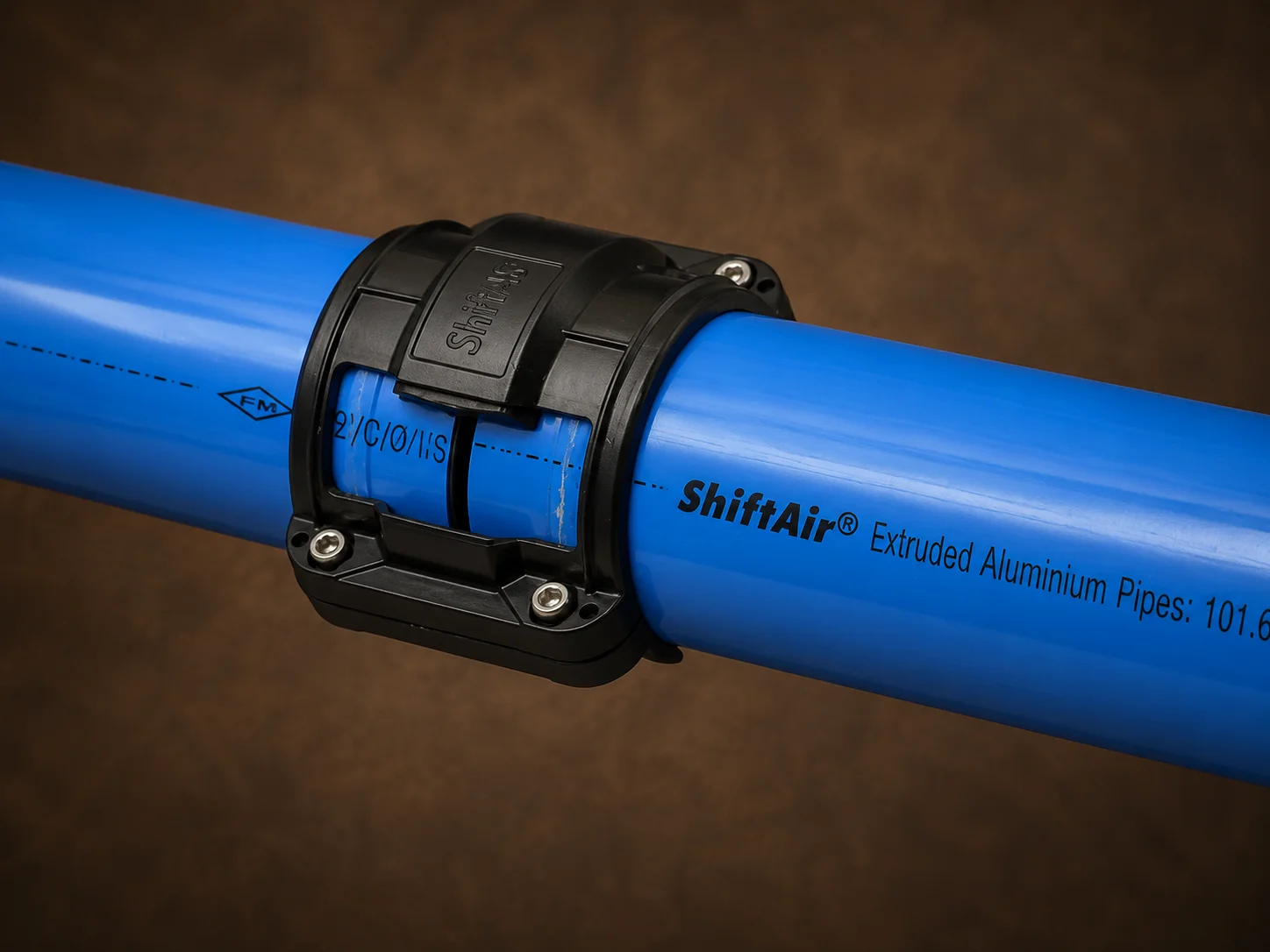
Compressed Air Pipe Installation: Step-by-Step Guide for Factory Projects
A practical engineering guide covering site surveys, layout planning, pipe sizing, mounting, installation, testing, commissioning and handover for industrial facilities across Delhi NCR and India.
A Compressed Air Network Must Be Engineered as a Complete System
A compressed air system is only as effective as the piping network that distributes air from the compressor room to production equipment.
Even when a factory has a properly selected compressor, an undersized, leaking or poorly routed pipeline can cause pressure loss, unstable machine performance, higher compressor loading and unnecessary production interruptions.
Professional compressed air pipe installation is therefore not limited to joining pipes and fittings. It is an engineering process that includes air-demand assessment, pipe sizing, routing, mounting, moisture management, isolation planning, testing and final commissioning.
ShiftAir Transmission Pvt. Ltd. supports compressed air piping projects in Faridabad, Delhi NCR and industrial locations across India. Project support can include modular aluminium piping, layout planning, supply, installation, testing, commissioning and expansion planning.
Eight Controlled Stages of Factory Air-Line Installation
Site Survey
Inspect the compressor room, machine demand, structural supports, safety conditions and shutdown requirements.
Layout and Pipe Sizing
Plan the main header, ring main or straight main, branches, drops, valves and future expansion points.
Material Selection
Select compatible pipes, fittings, seals, valves and accessories with suitable ratings.
Mounting Plan
Mark support points, clearances, valve access, drain locations and safe utility crossings.
Pipe Preparation and Installation
Cut, deburr, clean and assemble the main header, branches and machine drops.
Point-of-Use Connections
Install isolation, filtration, regulation and flexible connections at machine points.
Testing and Commissioning
Check joints, supports, leakage, pressure performance and operation under representative load.
Handover and Maintenance Notes
Provide as-built layouts, test records, valve identification and inspection guidance.
Why Proper Compressed Air Piping Installation Matters
Compressed air loses pressure as it moves through pipes, valves, bends, couplings and flexible connections. Friction, unnecessary changes in direction, restricted fittings and insufficient pipe diameter can increase this pressure loss.
A useful engineering objective is to keep pressure drop in the fixed distribution network low while also accounting for losses through hoses, couplings, filters and fittings. Final limits must be confirmed through project-specific calculations.
Operational Benefits
- Stable pressure at production machines
- More consistent pneumatic equipment performance
- Reduced leakage risk
- Lower unnecessary compressor loading
Maintenance Benefits
- Easier isolation and maintenance
- Cleaner and more organised distribution
- Faster future expansion
- Better access to valves, filters and drain points
Important Design Principle
The final network must be designed for the factory’s actual and future air demand, not only for the compressor outlet size.
Conduct a Detailed Site Survey
Every compressed air piping installation should begin with a physical site survey. The engineer should inspect the compressor room, air receiver, dryer, filtration system, production floor, machine locations, structural members, ceiling height and existing utility routes.
The survey should record
- Compressor capacity and discharge pressure
- Existing and proposed machine demand
- Peak and average airflow requirements
- Distance to the farthest point of use
- Existing pipeline condition
- Dryer, filter and receiver arrangement
- Planned machinery or production expansion
- Available pipe-support locations
- Restricted or hazardous operating areas
- Maintenance and emergency access
- Permitted shutdown windows
- Possibility of phased installation
For an existing plant, pressure readings should be taken near the compressor and at selected remote points while production equipment is operating. A significant difference may indicate leakage, undersized sections, restricted fittings or an inefficient layout.
Information the plant should provide before the visit
- Factory layout or floor plan
- Machine list and machine locations
- Required pressure for each machine
- Air-consumption data
- Compressor and dryer specifications
- Current and proposed operating shifts
- Future expansion plan
- Production shutdown availability
Plan the Pipeline Layout and Pipe Size
Once the air demand has been mapped, the engineer prepares the compressed air distribution layout. The design normally includes the compressor-room outlet, main header, ring main or straight distribution main, branch lines, vertical drops, isolation valves, drainage points, machine connections and future extension points.
Ring main or straight-line layout?
Where the plant layout permits, a closed-loop or ring-main network is often preferred. It can supply a point of use from more than one direction and can help improve pressure distribution across the production floor.
A straight main may still be suitable for a smaller workshop, linear production layout or isolated production zone. The correct configuration depends on distance, demand diversity, pressure requirements and future expansion.
Factors used for pipe sizing
| Design input | Why it matters |
|---|---|
| Required flow rate | Determines the volume of air that the pipe must carry. |
| Operating pressure | Affects air density, equipment performance and allowable pressure loss. |
| Total equivalent length | Includes straight pipe plus the resistance created by fittings and valves. |
| Peak simultaneous demand | Ensures the network can support multiple machines operating together. |
| Acceptable pressure drop | Defines the performance target from the compressor room to remote points. |
| Future capacity | Prevents premature replacement when production expands. |
Pressure-Drop Calculation
Pipe diameter should not be selected only by matching the compressor outlet. Long runs, peak demand, valves, bends and future additions must also be considered.
Use the compressed air pressure-drop calculator during early project planning.
Select the Appropriate Pipe Material
Material selection affects installation time, air quality, corrosion resistance, maintenance requirements and the ease of modifying the network.
Modular aluminium compressed air piping
Modular aluminium piping is widely selected for modern factory air-line installation because it is lightweight, resistant to internal corrosion and comparatively easy to modify. Its smooth internal surface can support efficient airflow when the network is correctly sized and installed.
Typical Advantages
- No internal rusting under normal intended service
- Lightweight handling
- Mechanical modular connections
- Faster modification and extension
Project Advantages
- Clean professional appearance
- Reduced dependence on welding and threading
- Easier relocation of machine drops
- Consistent system components
The selected pipes, fittings, seals and valves must have compatible pressure and temperature ratings. Mixing unapproved products or connection systems should be avoided.
Air-quality requirements
Food, beverage, pharmaceutical, electronics and other sensitive applications may require a defined compressed-air purity level. Pipe material is only one part of air-quality control; compressor type, dryers, filters, drains and maintenance practices must also support the required result.
Prepare the Mounting and Support Plan
Before pipe installation begins, the engineer should mark the route and finalise support locations. A mounting plan should identify bracket and clamp positions, structural supports, expansion allowances, valve access, safe electrical clearance, separation from heat sources, drainage points and protected crossing areas.
Support and Structure Check
Support spacing must follow the selected piping manufacturer’s instructions. Pipes should not be fixed to weak cladding, temporary structures or equipment that may vibrate. Heavy valves, filters and regulators may require independent support.
Prepare Tools, Materials and the Work Area
A controlled installation starts with material verification, safe work planning and correct tool preparation.
Before installation, pipe lengths and fittings should be inspected for transit damage, contamination or incorrect specification. Cut pipe ends must be clean, square and correctly deburred. Burrs or metal fragments can affect seals, restrict airflow or move towards downstream equipment.
Safety and permit controls
Compressed air is stored energy. Installation, modification and testing should be performed by trained personnel under the factory’s permit-to-work and lockout procedures.
- Isolation and depressurisation
- Working-at-height controls
- Barricading of the work area
- Approved access platforms and ladders
- Electrical-tool inspection
- Material lifting controls
- Eye and hand protection
- Controlled pressure testing
- Emergency response arrangements
Applicable Codes and Procedures
The competent project engineer must identify the correct code, plant standard and manufacturer procedure for the specific installation. Test values should never be copied from an unrelated project.
Install the Main Header, Distribution Lines and Machine Drops
Installation generally begins with the main header. The team marks the route, installs supports and then assembles pipe sections according to the approved drawing.
Controlled installation sequence
- Isolate and depressurise the existing network.
- Mark pipe routes and support points.
- Install brackets, clamps and independent equipment supports.
- Measure and cut the required pipe lengths.
- Deburr, clean and inspect each cut end.
- Assemble the main header using approved fittings.
- Install branch lines and isolation valves.
- Add vertical drops near production machines.
- Connect filters, regulators or point-of-use equipment where specified.
- Label valves and distribution zones.
The installer should avoid unnecessary elbows, sudden reductions and complex detours. Where a bend or direction change is necessary, its effect should already have been considered in the pressure-drop calculation.
Moisture and drop-line planning
Distribution design should prevent condensate from being carried directly into equipment. Drainage, dryer performance, filtration and machine take-off orientation should be considered together.
Where production areas need independent maintenance, isolation valves should divide the network into logical zones so one section can be serviced without depressurising the entire factory.
Connect machines and points of use
Each machine connection should be reviewed for:
- Required machine pressure
- Peak airflow
- Hose or flexible-connection size
- Filter-regulator requirements
- Isolation valve position
- Vibration or machine movement
- Maintenance accessibility
- Protection from impact
Do Not Ignore the Final Connection
A correctly sized main pipe can still perform poorly if the final hose, coupling, regulator or machine connection is too small. The complete flow path must be assessed up to the machine inlet.
Perform Leakage Testing and Commission the System
The newly installed system must be inspected before it is placed into production. Testing should follow the product manufacturer’s instructions, the approved method statement and applicable plant requirements.
Pre-commissioning checks
- Confirm that every joint is correctly assembled.
- Verify valve orientation and accessibility.
- Check pipe supports and bracket security.
- Remove tools and installation debris.
- Isolate sensitive downstream equipment where required.
- Pressurise the network in a controlled manner.
- Inspect joints and connections for leakage.
- Record pressure at the main header and remote points.
- Confirm drain and condensate arrangements.
- Rectify leaks before final acceptance.
Testing Safety
Test pressure must not be guessed. No joint should be tightened, disconnected or repositioned while the network remains pressurised.
Commission under operating load
A leak-free static test does not confirm that the network will meet production demand. Performance should therefore be checked while representative machines are operating.
- Pressure at the compressor-room outlet
- Pressure at remote machine points
- Behaviour during peak demand
- Dryer and filter performance
- Valve operation
- Air supply to critical machines
- Absence of abnormal vibration
- Acceptable network pressure drop
Where performance differs from the design, the team should check restrictions, closed valves, undersized hoses, regulators, filters and local high-demand equipment before increasing compressor pressure.
Complete Technical Handover and Documentation
A professional installation should finish with technical handover rather than only physical completion.
Handover Documents
- Approved or as-built layout
- Pipe-size schedule
- Valve and drop-point identification
- Product technical data
- Pressure and leakage test records
Operational Support
- Commissioning readings
- Warranty information
- Operating instructions
- Recommended inspection schedule
- Future expansion provisions
Plant maintenance personnel should be shown how to isolate sections, inspect fittings, operate drains and safely add approved extensions.
Plan Installation Around Factory Downtime
Downtime should be discussed during the initial survey—not after material reaches the site. For an operating factory, the project may be divided into:
- Off-line prefabrication and support installation
- Main-header installation above operating zones
- Branch installation in phases
- Final tie-in during a planned shutdown
- Zone-wise testing and commissioning
- Temporary supply arrangements where technically feasible
Actual downtime depends on the existing network, plant layout, connection method, production requirements and safety restrictions. A credible proposal should state which activities can occur during production and which require isolation.
Avoid Unsupported “Zero Downtime” Claims
Any shutdown commitment should be supported by an approved method statement, contingency plan and clear technical assumptions.
Maintenance Notes for the Compressed Air Network
Even a properly installed compressed air network needs planned inspection.
- Inspect joints, valves and machine drops.
- Monitor pressure at reference points.
- Check for audible and ultrasonic leakage.
- Examine brackets and clamps.
- Inspect condensate-management systems.
- Review filters and regulators.
- Check flexible hoses for damage.
- Update drawings after modifications.
- Verify unused connections are isolated.
- Investigate unexpected increases in compressor running hours.
Expansion work should use compatible, manufacturer-approved fittings and follow the same isolation, safety and testing controls as the original installation.
Compressed Air Pipe Installation in Delhi NCR and Across India
ShiftAir supports factory air-line installation requirements in Faridabad, Ballabgarh, Gurugram, Manesar, Noida, Greater Noida, Ghaziabad, Bhiwadi, Neemrana, Sonipat, Kundli and other industrial locations.
Pan-India project requirements can include
- New factory projects
- Production-line expansion
- Compressor-room relocation
- Replacement of old GI or MS pipelines
- Ring-main development
- Additional machine drops
- Pipeline leakage correction
- Plant utility modernisation
Project feasibility, site visits, installation scheduling and deployment are assessed according to location, technical scope and plant operating conditions.
Arrange an Engineer Site Visit
Planning a new factory air line, replacing an old pipeline or expanding your compressed air distribution system? ShiftAir can assess the plant layout, air demand, operating pressure, machine points, pipe-size requirements and installation schedule.
Useful details to share: factory location, industry, compressor capacity, operating pressure, approximate pipeline length, number of machine points, installation type and shutdown availability.
Compressed Air Pipe Installation FAQs
Continue Your Project Research
Reference Standards and Guidance
- Atlas Copco: Compressed Air Distribution
- ISO 8573-1: Compressed Air — Contaminants and Purity Classes
- ASME B31.3: Process Piping
Technical references provide general context. Final engineering decisions, test procedures and installation methods must be approved for the specific site, piping system and operating conditions.