
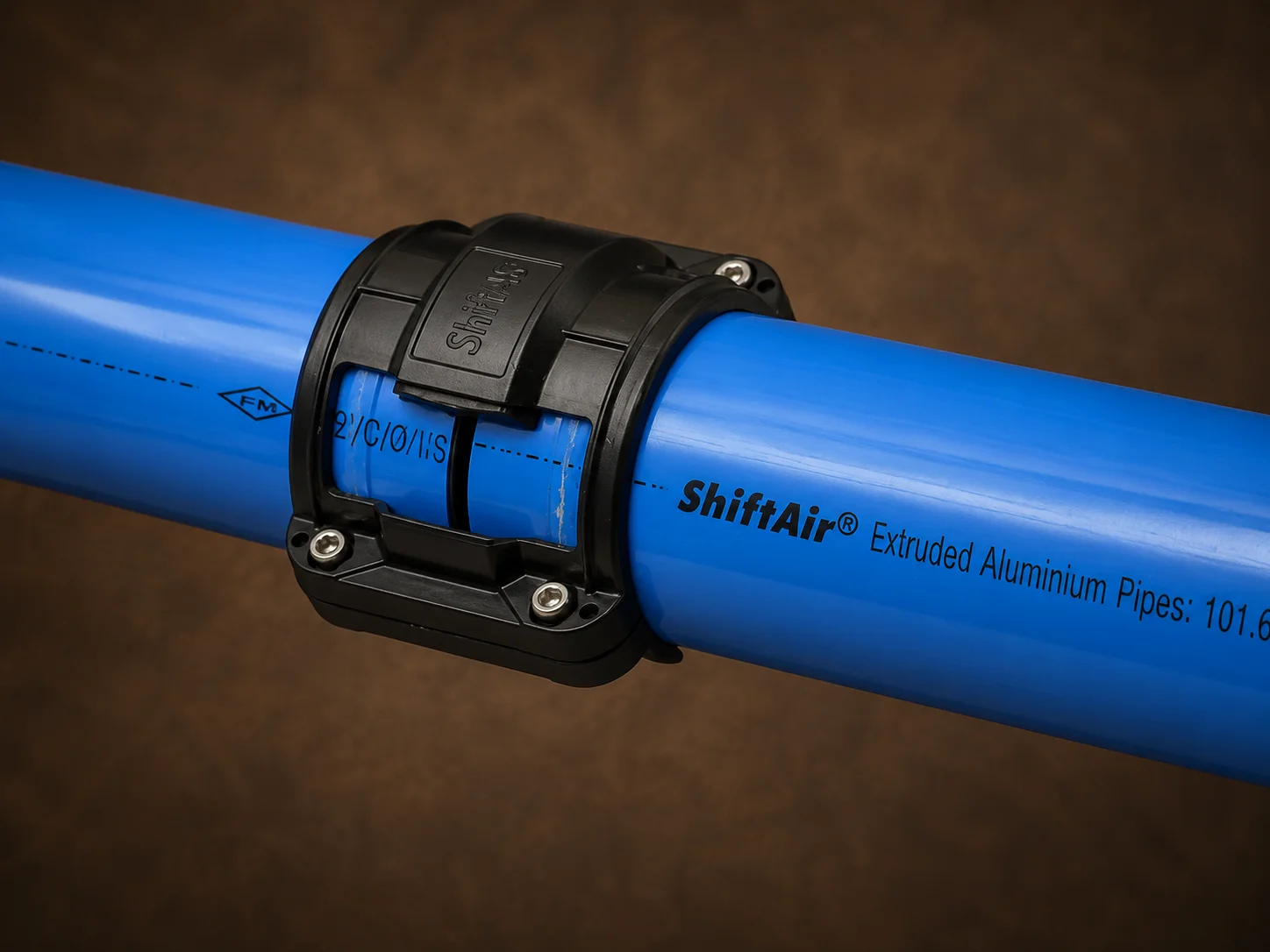
A ring main and a branch line can both distribute compressed air, but they behave differently when several machines demand air at the same time. A ring main supplies a point of use from two directions, while a branch line normally supplies it through one route. The better design depends on airflow, factory shape, operating pattern, expansion plans and acceptable pressure drop.
Choose a ring main whenSeveral production areas operate simultaneously, pressure stability is critical, demand changes frequently or future expansion is expected.
Choose a branch line whenThe system is small, the route is short, demand is predictable and only a few machines require compressed air.
For many medium and large factories, the most practical answer is not ring main or branch line alone—it is a correctly sized ring main with engineered branches and machine drops.
Ring Main vs Branch Line: What Is the Core Difference?
In a branch line, air moves from the main supply pipe toward the machines through a single directional route. The final user is affected by the pressure loss created along that complete path. In a ring main, the main pipe forms a closed loop around the production area. Branches or drops connect machines to this loop. Air can approach a demand point from both sides of the ring, which can reduce the load carried by any one section and support more uniform distribution.| Design factor | Ring main | Branch line |
|---|---|---|
| Airflow path | Air can reach users from two directions | Air normally travels through one route |
| Pressure stability | Usually better across multiple demand points | More sensitive to distance and simultaneous demand |
| Initial pipe length | Usually higher | Usually lower |
| Expansion flexibility | Strong when spare capacity is planned | Suitable for limited extensions; major growth may require redesign |
| Isolation | Sections can be zoned with correctly placed valves | Downstream users may be affected when an upstream section is isolated |
| Best suited to | Medium and large plants, changing loads and several production zones | Small workshops, short routes and isolated users |
How Does a Compressed Air Ring Main Work?
A ring main is a closed-loop header routed around a production area. Instead of ending at the last machine, the main pipe reconnects to itself. Machine branches are taken from selected points around the loop. When a machine starts consuming air, the ring can feed that point through clockwise and anticlockwise paths. The actual split depends on pipe sizes, route lengths, fittings, pressures and demand elsewhere in the network.Main advantages of a ring main
- More balanced compressed air distribution across the plant
- Lower dependence on one long flow path
- Improved pressure stability during simultaneous demand
- Greater flexibility for adding future branches and drops
- Opportunity to isolate a section while maintaining supply through another path, if the valves and layout are designed for it
- Better suitability for production halls with machines located around the perimeter or across multiple zones
Limitations of a ring main
- Greater initial pipe length and additional fittings
- More engineering effort during layout planning
- More isolation valves may be required for effective zoning
- A badly sized ring can still experience pressure drop
- An unnecessarily large ring may increase capital cost without providing a meaningful operating benefit
Important: A ring shape does not automatically make a system efficient. Diameter, total demand, diversity, route length, fittings, pressure and future load must still be calculated.
How Does a Compressed Air Branch Line Work?
A branch-line or tree layout begins with a main supply pipe. Secondary pipes divide from the main and continue toward individual machines or production areas. Air usually follows one path from the compressor room to each point of use.Main advantages of a branch line
- Lower initial pipe quantity for a simple layout
- Easy to understand in a small workshop
- Practical for a short row of machines
- Suitable for a remote or isolated user located away from the main plant
- Can be economical when demand is low and unlikely to grow
Limitations of a branch line
- The farthest machine receives air through the longest single route
- Simultaneous demand can produce a greater pressure difference between near and distant users
- An upstream restriction or isolated valve can affect every downstream user
- Repeated extensions may turn the system into an unplanned network of undersized branches
- Future production changes may require larger sections to be replaced
Detailed Design Comparison
| Parameter | Ring main | Branch line | Design implication |
|---|---|---|---|
| Simultaneous machine demand | Handles distributed demand more evenly when sized correctly | Demand accumulates along the single supply path | Study peak coincident demand, not only compressor capacity |
| Distance to final user | Effective flow path may be shared from both sides | Last user depends on the complete upstream route | Long branches need careful diameter verification |
| Production expansion | New take-offs can be planned around the loop | Additional users increase load on existing upstream pipe | Reserve capacity must be deliberate, not assumed |
| Maintenance zoning | Strategic valves can isolate sections | Isolation can interrupt all users beyond the valve | Prepare a valve and shutdown philosophy |
| Installation complexity | Higher | Lower for a simple route | Compare lifecycle value with initial cost |
| Layout suitability | Open production halls and multiple departments | Small workshops, single rows and isolated equipment | Plant geometry should guide topology |
| Failure sensitivity | Alternative flow path may remain available | Single route creates greater downstream dependence | Redundancy depends on isolation design and system condition |
| Leak management | More pipe and joints to inspect, but sections can be zoned | Fewer components in a basic system | Neither layout replaces a leak-management programme |
Which Layout Provides Better Pressure-Drop Performance?
A ring main usually provides better pressure distribution because the demand point can receive air from two directions. However, its performance depends on engineering—not the label applied to the layout. Pressure drop is influenced by:- Airflow through each pipe section
- Internal pipe diameter
- Total equivalent length
- Working pressure
- Elbows, tees, valves, hoses and couplings
- Internal surface condition
- Leaks and restrictions
- Peak simultaneous demand
Ring Main vs Branch Line: Installation and Lifecycle Cost
A branch line normally requires less pipe in a simple installation, so its initial cost may be lower. A ring main closes the loop and may need more pipe, valves, connectors and supports. Initial price is only one part of the decision. Lifecycle evaluation should also consider:- Energy associated with pressure loss
- Cost of production interruption during modifications
- Ease of adding machines
- Maintenance access and isolation
- Need to replace undersized upstream sections
- Leak inspection and repair requirements
Why a Hybrid Layout Is Often the Best Industrial Solution
In practice, many effective factory networks combine both layouts:1Main ringA closed loop distributes air around the primary production area.
2Zone branchesEngineered branches feed departments, machine groups or remote areas.
3Machine dropsSmaller vertical drops connect individual points of use with suitable valves and treatment.
Which Layout Works for Different Indian Factory Conditions?
| Factory scenario | Likely starting point | Reason |
|---|---|---|
| Automotive assembly plant | Ring main with zoned branches | Many simultaneous tools, changing lines and pressure-sensitive production |
| CNC workshop with six machines | Branch or small ring after calculation | Decision depends on distance, usage pattern and expansion plan |
| Food or pharmaceutical facility | Engineered ring or hybrid network | Stable distribution, isolation, cleanliness and planned drops are important |
| Textile production hall | Ring main | Distributed demand and multiple machines operating together |
| Packaging line in one straight bay | Properly sized branch may be sufficient | Short, linear layout with predictable users |
| Large plant with separate buildings | Multiple zoned rings connected by engineered headers | Better control, isolation and future expansion |
| Occasional-use maintenance shed | Dedicated branch | Low, intermittent demand may not justify a complete loop |
How to Design the Right Compressed Air Layout
Step 1: Map every air consumer
Record machine location, connection size, required pressure, average flow, peak flow, duty cycle and air-quality requirement.Step 2: Determine simultaneous demand
Do not simply add every nameplate flow if all machines do not run together. At the same time, do not use an optimistic average that ignores peak production periods. Develop a realistic demand profile.Step 3: Mark the compressor room and treatment equipment
Include compressors, receivers, dryers, filters, drains and the point where treated air enters the distribution network.Step 4: Develop alternative routes
Prepare at least a branch option and a ring or hybrid option for medium and large plants. Check pipe length, obstruction count, installation height and access.Step 5: Size each section
The main ring, interconnecting headers, zone branches and machine drops do not necessarily require the same diameter. Calculate flow through each section and verify pressure loss to critical users.Step 6: Plan valves and maintenance zones
Decide which production areas must remain operational when another section is maintained. Place isolation valves accordingly and ensure they remain accessible.Step 7: Address condensate and air quality
Routing, take-off orientation, drainage and point-of-use treatment must be designed for the actual air quality and moisture conditions. Follow the piping manufacturer’s installation instructions and applicable plant standards.Step 8: Reserve capacity deliberately
Identify confirmed or probable future machines. Oversizing without reason can waste capital, while ignoring known expansion can create premature replacement cost.Step 9: Validate installation conditions
Check structure, supports, height, electrical routes, fire systems, cranes, heat sources, hygiene zones and production restrictions before finalising the bill of quantities.Step 10: Test the completed network
Inspect joints, supports, valves and routes; conduct the required pressure and leakage checks; and verify performance at representative points of use.Common Ring Main and Branch Line Design Mistakes
- Assuming every closed loop will have low pressure drop
- Sizing the entire network from compressor outlet diameter
- Ignoring peak simultaneous demand
- Adding new branches without checking the upstream capacity
- Using long flexible hoses as permanent distribution lines
- Installing too few isolation valves—or placing them where they cannot be reached
- Routing the main around obstacles without considering equivalent length
- Connecting sensitive users without reviewing air quality and point-of-use treatment
- Ignoring drainage and condensate management
- Failing to document the final installed network
Final Selection Checklist
A ring main is generally the stronger candidate when:- Many machines operate simultaneously.
- Pressure consistency across departments matters.
- The production layout changes regularly.
- Future branches and machine drops are expected.
- Maintenance zoning is operationally valuable.
- The network is short and simple.
- Only a few points of use are connected.
- Demand is low and predictable.
- The equipment is remote from the primary production area.
- Future expansion is unlikely.